This page is intended to show the thinking that led to the design of the Tubelab SE. I never intended for any of these designs to become a complete stereo amplifier that could be duplicated by a beginner. All experiments were carried out using bench power supplies, and no power supplies or complete amplifiers were ever built. All three of these circuits were assembled and tested as a single channel test amp. They all work as shown. Any of these designs could be the starting point for a complete stereo amp, but I never took them that far. I have received dozens of e-mails asking for the complete construction details, I am sorry to say that there are none.
The Simple 45 began as the starting point for a "Super Tube" amp design. I needed a simple single ended amplifier with excellent sound. The Simple 45 started out as a basic two stage single ended 45 amp. The design has matured into a sweet sounding 2 watt SE amp. The three best sounding designs are presented on the this page. The fourth (and final) design is the Tubelab SE amplifier, which now has its own page. At this time the complete stereo amplifier including power supply has been implemented on a single PC board.
Why a 45 Amp? The 45 is one of those tubes that is highly regarded by Single Ended Audiophiles. I want a single ended amp that puts out around 2 watts as the starting point for "super tube" experiments. Since this amp would evolve into a hybrid "super tube" amp, the sound quality must be excellent. The 45 is the lowest priced "audiophile triode" that I could find. I got three 45 tubes on Ebay for $11.51 because they were sold as "in fair shape, one is between good and bad". This qualifies as cheap, so I decided to build a single ended 45 amp. The 5842 tubes were found in my collection of "useless TV tubes". The output transformer is borrowed from the Ongaku project (extreme overkill). The schematic shown below was my "first cut" at a 45 SE amp. It produces excellent sound and would make a nice 1.5 watt 45 SE amp as shown. Several iterations of 45 amp designs have been tried and a few are presented here.
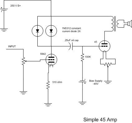
The Original Simple 45 Design
This is the first iteration of the design. The unique feature is the use of constant current diodes as the plate load on the input stage. This provides lower distortion and higher gain than the conventional resistor. I started with a resistor but there just wasn't enough gain, and the sound seemed to lack something. I know that the ideal load for a triode is a current source so I put a constant current diode in place of the plate load resistor. One diode didn't pass enough current so I used two, and then three. Two worked the best. The diodes are available from Mouser in several values up to a few milliamps. Since the schematic was drawn I have added an electrolytic capacitor across the 510 ohm cathode resistor to raise the driver gain.
The amp is still in the design phase (on Tubelab of course), but the sound is already excellent (all 2 watts of it). I have found that the sound quality can be improved by adding a resistor in series with the diodes (about 2K ohms).
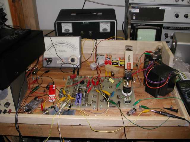 The Simple 45 as it was first conceived on the Tubelab2 prototyping system
I just acquired an FFT analyzer program that runs on your PC using the sound card for an input. The companion signal generator program uses the sound card for an output. This software is extremely useful for anyone who is involved in the design, testing, or tweaking of audio amplifiers. See the section on amp testing for full details on how this works. All of the plots on this page were done with this software.
Improvements on the Simple 45 Design
I decided to experiment with several different current source designs since I wasn't completely happy with the operation of the constant current diodes. I don't like the fact that I need the resistor in series with them and the resistor value is pretty touchy. They are operating at 104 Volts which is above their maximum ratings (100 Volts max). What is needed is a circuit which can provide a constant current over wide voltage range, provide a high dynamic impedance, and operate with a low voltage across the circuit.
I tried several vacuum tubes as current sources and found that the only tube which could hold a constant current over a wide voltage swing is the 5879. Unfortunately this only holds true for currents of 4 mA and less. Currents above 5 mA require more than 50 Volts to operate. The usual 12BY7 works ok at low voltages but the current varies too much over the needed voltage swing. These might be great in an amp that has a higher voltage source available, but not here.
I tried the usual mosfet current sources with good results, although the current is not as constant as I had hoped. All of the mosfets that I have available are enhancement mode devices (the most common mosfet). These devices are in the off state with zero bias applied, not optimum for a current source. There are a few depletion mode devices in the world but I could not find any in stock at the usual distributors. These devices are in the on state with zero bias, and behave much like a pentode vacuum tube. Excellent for a current source, but that doesn't help if I can't get any.
I was considering designing a circuit with an opamp and a mosfet to create a constant current source when I found an IC that already does this. I placed an order, which was immediately back ordered. I will definitely try these when they show up.
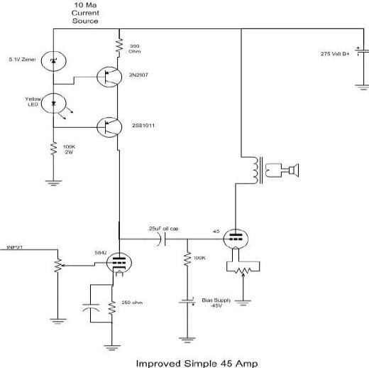
I also experimented with active current sources using bipolar transistors. The classic circuit with a zener diode on the base and a resistor on the emitter works good. Stacking two or more of these circuits in series raises the voltage handling capability, but this must be done in a way to insure proper voltage sharing. The alternative approach uses a small high beta transistor to set the current, and a high voltage transistor to handle the voltage and dissipate the power. I have found several variations of the same circuit on the web, all pretty much the same except for the trick of using an LED for a low voltage zener. The physics of zener diodes does not allow their operation below 3.9 volts. I don't like using an LED for the zener on the low power transistor, it really wants 4 or 5 volts to work right. So far the circuit I breadboarded works the best and it is now in the amp.
While searching the web for current source chips and circuits I found several compound circuits using tubes, mosfets, and transistors. I have not tried any of them, perhaps one of them would work well here.
This iteration of the Not Quite as Simple 45 Amp performs better than the original design. The distortion spectrum and the IMD looks like the amp above when it was tweaked out perfectly, however it needs no tweaking. I tried adding a resistor and it had no effect until the value is large enough to cause the current to drop. Given that the driver runs at a constant 10 mA (which can be raised) it presents a low enough impedance to drive the grid of the 45 positive for A2 operation. Operation in this manner yields 2.4 watts of power at 9% distortion. It sounds amazingly good considering the distortion.
More Improvements on the Simple 45 Design
The CCS IC's have arrived. I know that there are a few die hard tube heads out there that are going to have a hard time putting an integrated circuit in a vacuum tube amplifier. All I have to say is that these things cost less than most tweaks and sound awesome. Try using one of these in place of the plate load resistor on any low level triode amplifier stage. These won't work well with pentodes, or multi stage direct coupled circuits (like the SRPP). The sound quality is better than any of the other CCS circuits that I have tried. If you don't like the sound, put the resistor back. It was a cheap experiment.
A few other modifications have also been made. The amp had an almost unidentifiable fogginess to it that the FFT analyzer revealed as residual 60Hz hum. The hum was not audible by itself in the speakers but showed up as intermodulation products. This was cured by operating the 45 filament from a DC power supply. The operating point of the 45 was shifting as the stage approached clipping. The current through the 45 actually decreased, which caused clipping to occur too early. This was cured by reducing the value of the grid resistor. The 5842 seemed happier with 12 mA of current which required reducing the cathode resistor to 240 ohms. The 10M45 chip can oscillate under some conditions which was fixed by adding a "stopper" resistor of 1K ohms to the "G" terminal.
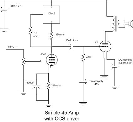
The Not Quite as Simple, but Way Better 45
The schematic of the amp as it exists today is here. It was my intention to use this design as a starting point for "super tube" experiments. The amp surprises me with its sound quality. My speakers are only rated at 87db efficiency. With 2 watts of power you can't get real loud. Within the power limits I can say that this design has sound that rivals any amp that I have built.
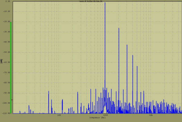
Below is the distortion spectra for the completed amplifier:
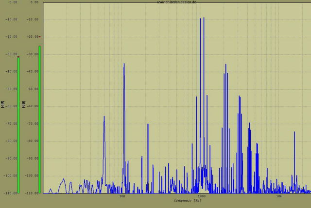
The IMD plot:
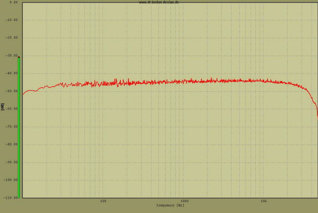
This is the frequency response for the amp:
Since this design was started I have taken a deeper interest in single ended amplifier designs. This design began as the basis for a hybrid amplifier, which continues on the Super Tube SE page. The Super Tube design will receive further attention shortly. In the process of developing this design I became so impressed with the sound, that I decided to further develop it into a complete amplifier, the Tubelab SE . See that page for the complete design. A PC board based complete amplifier has also been designed, see the SE AMP PC board page, I intend to make these available for sale shortly.
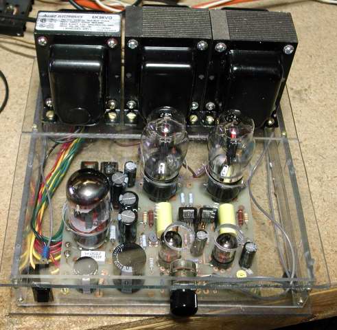 Combine one board, 3 transformers, and some type of enclosure and you have an amp, a very good amp
What's Next
At one time I said that I wasn't going to build this amp. Well this amp evolved into the Tubelab SE amp, and I have built 9 of them so far and more are currently under construction. I have also used one of these as a driver for a 40 watt per channel monster 845SE amp. I originally designed this amp as a building block for a hybrid amp. At that time I had not paid much attention to the whole single ended craze. After building one of these I found myself listening to it, and listening to it, and listening to it some more. Then I built another one. Then I had to build a bigger one (the 845SE amp). Now I am actually considering building an even bigger one using 833A's. The prototype has already been built.
I can't explain the theoretical reasons for the sound that I am hearing but it is different from anything that I have heard from a push - pull amp, even a class A 300B push - pull amp. There is a clarity that you don't get from the push - pull design. All is not perfect however, the bass is not as "in your face" as the 300B push - pull amp. This is especially noticeable with techno type music. The punch of a bass drum is more realistic through the 300B amp, but the snap of a rim shot, or a snare drum sounds much better on the single ended amp.
I will eventually return to designing and building push - pull amps, but for now I am searching for the magic amp design that will sound like the Tubelab SE, have the bass dynamics of the 300Beast, and have plenty of power without requiring a bigger air conditioner. I am not sure that such an amp is possible, but whatever I come up with, you will read about it on this web site.
Update
I get a lot of e-mail about this design. Many people like it because it is simple. I have explained that the prototypes don't exist anymore, but people want to build it. What is my advice? Which one do I build? What can I use in place of the 5842? Can I use cathode bias?
Here are my EDUCATED GUESSES. I have not actually built these designs, but these are good places to start. The second or third designs sounded the best. Start with the one that you can get parts for. If you can get the IXYS 10M45S in your country, then build that design. Due to the scarcity of reasonably priced 5842's, I have been looking for a different tube that works as good as the 5842. Unfortunately, I haven't found one. I have been using 12AT7's in my latest amp designs. It comes real close to the 5842's performance. I use 1/2 of the tube for each channel, bias it at the same 10mA. The cathode resistor needs to be 220 ohms. There is no reason that you can't use cathode bias in these designs. You would need 2 floating filament supplies (or two windings on a transformer) and about 30 to 50 volts more B+ voltage.
I haven't actually built any of these designs using DHT's. I am not likely to have the time to do so in the near future. I am providing the information in this update for those who have asked me these questions via e-mail.
I HAVE built a complete stereo amp based on this work that uses common audio tubes (6L6, EL-34, KT-88) in triode or UL configuration. It is coming to this web site soon.